Fraunhofer Institute for Mechanics of Materials IWM
Tribology at component level
Tribology at component level
Friction and wear are system variables and not material properties. For the assessment of the tribology of components, a middle way therefore often has to be found that which allows remaining as close as necessary to the real system and still making friction and wear values accessible, carrying out the test with a manageable amount of effort.
Numerous model, component and system test benches are available at the Fraunhofer IWM, covering a very broad field of applications. These include very large and very small normal forces (5 mN to 250 kN), rotating and reversing movements, oscillating and fretting stresses, high-temperature test stands and tribometers that can be operated in defined atmospheres from UHV to hydrogen. This page describes some of the equipment available at the Fraunhofer IWM in Karlsruhe. Please contact us with your specific question!
Selection of our machines and equipment in this subject area
The fretting tester
Fretting describes both wear and corrosion damage caused by high loads and repetitive relative movements with small amplitude δ (e.g. vibration) of two or more bodies. The Frettingtribometer at IWM allows us to reproduce and investigate such problems. The basic unit consists of three extremely stiff guide elements embedded in a massive natural stone table of the machine. The upper plate, which can be moved in a vertical direction, contains the lateral force sensor and a sample holder. The drive module for vibration generation with displacement measurement via a glass scale is located on the level below the lateral force sensor. The lower friction sample is mounted on the drive module. To analyze the energy dissipation in the contact point, the individual hysteresis loops are evaluated. For this purpose, force and displacement signals are recorded up to 250 kS/s. The displacement measurement via glass scale and the friction force measurement via piezo allow the precise measurement of a hysteresis curve even at high frequencies up to 500 Hz. Contact resistance measurement (four point) provides additional information about the processes in the contact point by means of contact resistance measurement.
The geometries of the samples range from standardized geometries (cylinder, ball, etc.) to original parts which are in use (connectors from the automotive sector). In this way, pure material pairings can be tested in advance and finished components can be tested for their behavior under vibration and for their service life. With its various specimen holders, the device also enables the examination of reversing contacts independently of a fretting load.
Technical data
| Parameter | Value | ||
| Amplitude | 1 to 12 000 µm | ||
| Normal force | 10 to 500 N | ||
| Frictional force | -500 to 500 N | ||
| Frequency range | 1 to 500 Hz | ||
| Sample rate | up to 250 kS/s | ||
| Resistance measurement | |||
| Sample rate | 80 Hz at 1 µΩ | ||
| Measuring range | 1 mΩ at 20 kΩ | ||
| Resolution | up to 1 µΩ ± 0,1% | ||
Microfretting measurements
The integration of a piezo stage into a nanoindenter allows fretting measurements under small loads in the range of less than 10 mN to > 2 N and amplitudes from < 1µm to 45 µm. Forces can be controlled with a high resolution in the mN range in all three spatial directions. The integration into the nanoindenter allows a highly accurate sample positioning and a load controlled experiment. The installation of a contact resistance measurement enables the characterization of switches and contacts that are exposed to fretting stresses.
What we offer
- Performance and analysis of Fretting experiments
- Wear measurement by means of white light interferometry
- Generation of friction maps
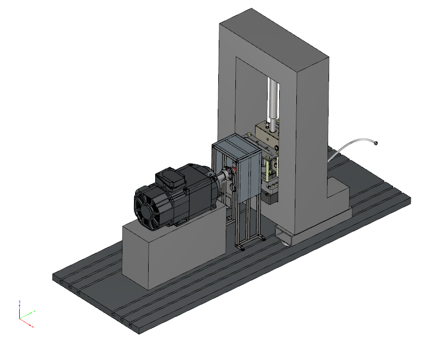
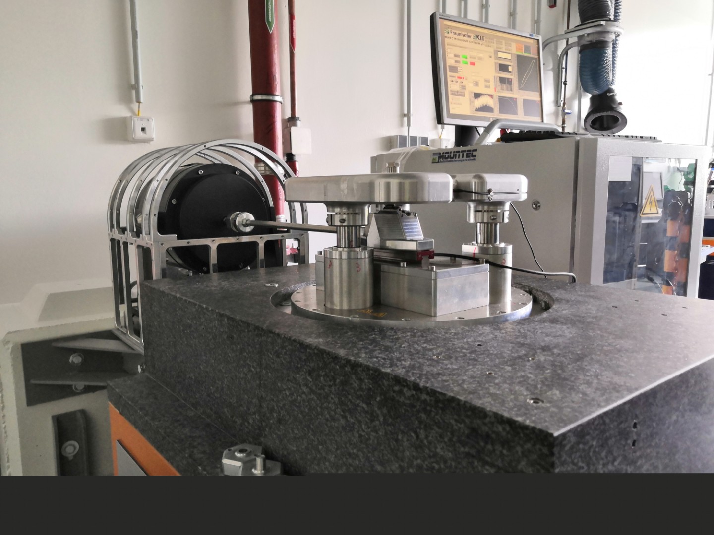
Plain bearing test rig up to 250 kN
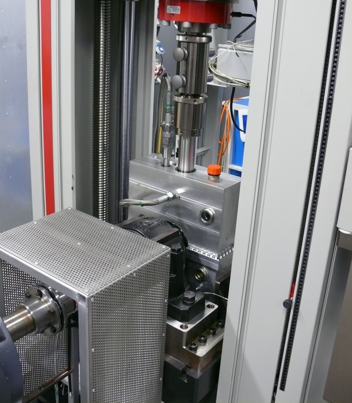
At the Fraunhofer IWM, a plain bearing and component test stand is available which also allows the coupling of large plain bearings up to 120 mm diameter and larger as standard. The test stand is extremely flexible due to the tension testing machine (normal force) and e-machine (rotation) modules and, after adaptation, allows the measurement of a wide range of geometries in combination with radionuclide technology (RNT). For example, oil screenings and wear tests on a bevel gear pair are also possible. The illustrations show a sketch of the overall test stand and a photo of the oil chamber in the tensile testing machine.
Typical fields of application of the test stand are wear tests on plain bearings depending on finishing and materials, lubricants and operating points. Real-time wear measurement under low loads and oscillating movements is just as possible as the identification of critical operating points and their influence on the stability of the plain bearing.
Key figures |
|
Speeds |
1- 800 [3000] rpm |
Torque |
max. 150 Nm |
Normal force |
250 kN |
Shaft diameter |
10 > 450 mm |
Oil temperature |
max. 100 °C |
Piston ring cylinder simulator
The conditions at the top dead centre of a cylinder are the most demanding for the tribologically loaded materials in terms of wear resistance. The piston ring cylinder simulator at the Fraunhofer IWM is suitable for friction and wear tests on liners and piston rings. In the device, samples from original components can be tested in reversing contact under temperatures of up to 180 °C. Piston ring segments can be tested against liner segments prepared directly from bushings or engine blocks. The tests can be carried out under frequencies up to 50 Hz, normal forces up to 400 N and a maximum stroke of 3 mm.
Tribometer farm
The tribo farm is a suitable method for understanding and characterising complex tribological data fields. The tribofarm is a combination of 16 identical tribometers, four of which are combined to form a unit (block). By varying the experimental conditions, it is possible to analyse parameter fields and conduct reproducibility studies through similar experiments. Tribological systems often operate in the lowest wear rate regime. Measurements can be implemented either with radionuclide technology (with the given advantages) or over correspondingly long test durations. With measurements over 7-10 days, the wear can also be determined ex-situ in the lowest wear rate regime using various methods. The parallel measurement of different systems enables a sufficiently good throughput in acceptable time periods.
In order to meet current research and applications, the blocks have been partially modified. The device specifications of the individual blocks can be found in the overview.
Technical data
| Unit specification | Block 1 | Block 2 | Block 3 | Block 4 |
| Type of contact | Sliding contact (pin-disc) | Sliding contact (pin-disc) | Rolling contact (axial deep-groove ball bearing) | Sliding contact (pin-disc) |
| Lubrication | Splash lubrication | Splash lubrication | Circulating or splash lubrication Splash lubrication | Splash lubrication |
| Speed in rpm | 1-900 | 1-900 | 1-900 | 1-1600 |
| Normal force in N | 0,6 | 0,6 | 4,7 | 0,6 |
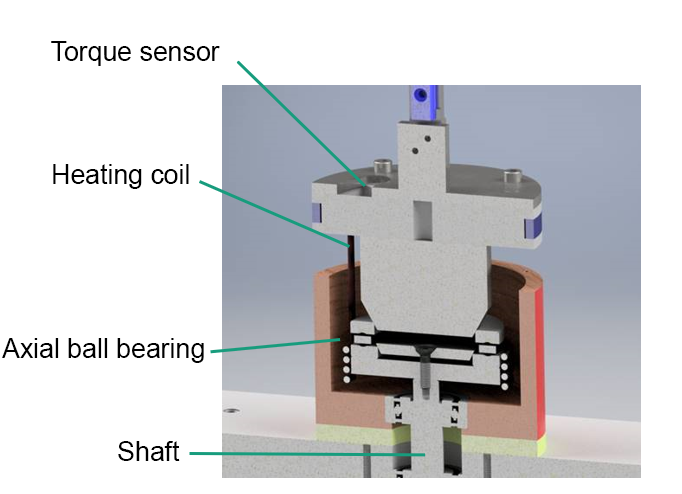
In the exemplary consideration of block 3 (rolling contact), the ball bearing is stressed with a normal force by the weight of the sensor holder and rotated by the coupling of the lower bearing ring with the drive shaft (compare figure 1). In addition, the oil is regulated to the desired temperature with a heating coil in the oil reservoir by a PID controller. The torque is measured in the sensor holder and used for the tribological evaluations.
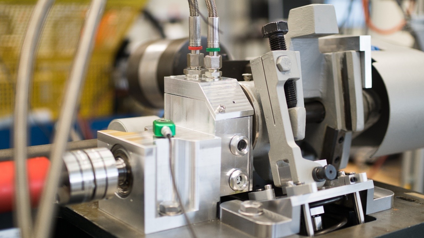
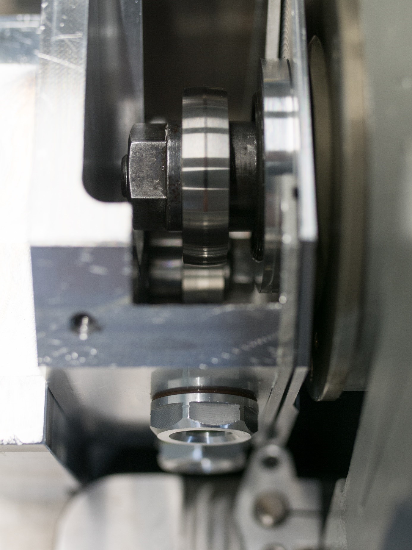
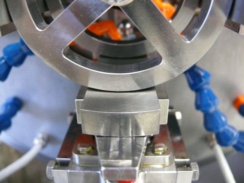
Twin-disc test stand
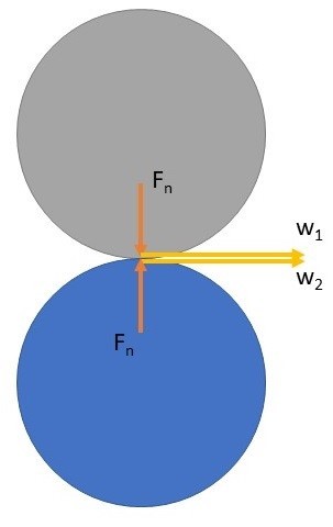
A twin-disc test rig is available at the institute for the defined examination of rolling contacts and rolling contact fatique (RCF). Among other things, this is being developed as an analogue test rig for gear wheels. Two discs are clamped against each other with a force Fn (Figure 1). Due to the difference in speed or sample diameter, the system experiences a slipping rolling motion.
The test stand received a comprehensive modernization in 2020. The entire measurement technology was renewed and expanded. The speed can be varied continuously between 45 and 600 rpm.
The normal force can be regulated between 80 and 1500 N. The samples have a diameter of 42 mm and a thickness of 10 mm. The resulting pressures as well as the slip can be changed by varying the specimen geometry (diameter, crowning).
Due to the design of the oil pan (Fig. 3, 4), there are various possibilities in the choice of intermediate media. The tests can be carried out lubricated (circulating and immersion lubrication) and unlubricated. In addition, real-time wear measurements using radionuclide technology are possible on this test rig.